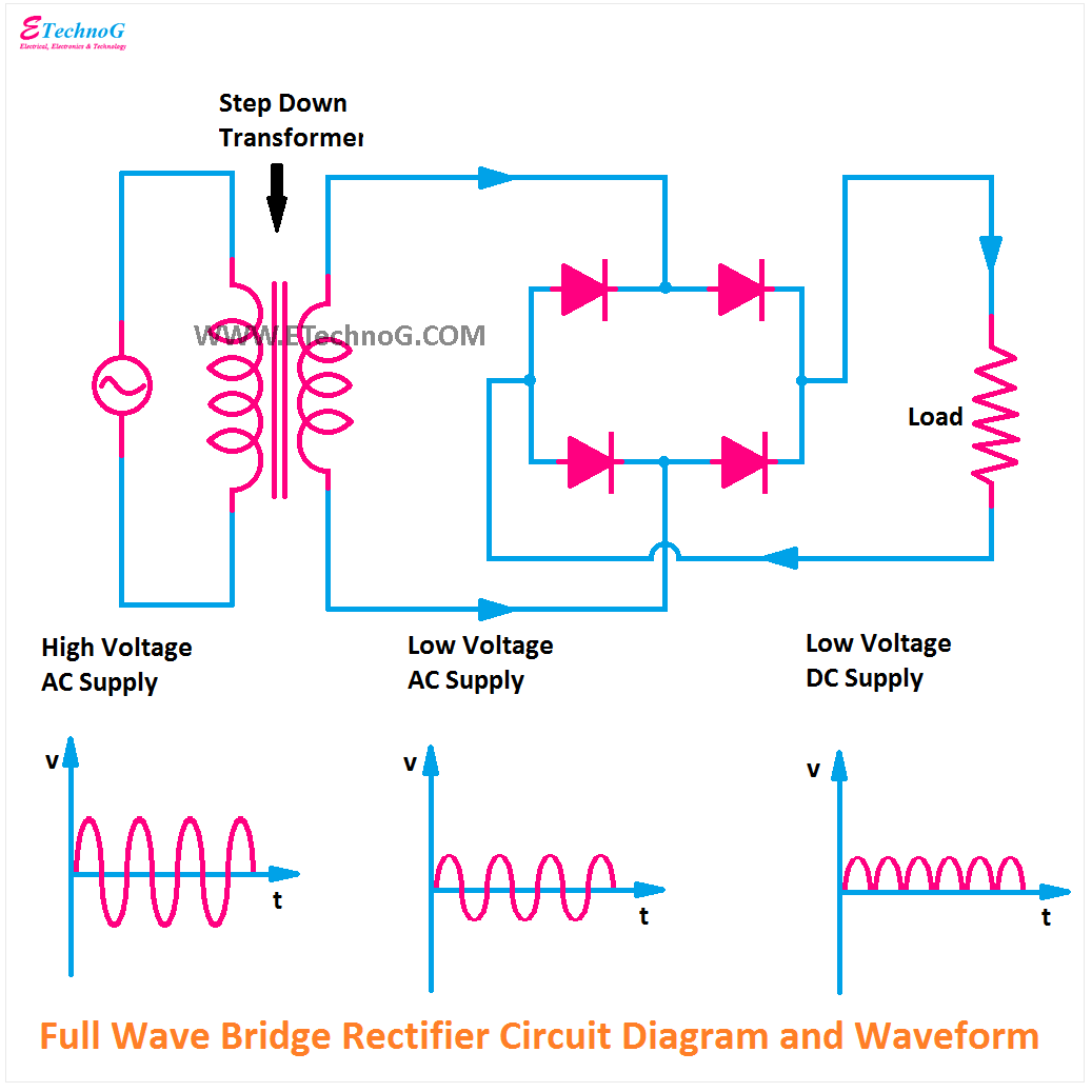
Full Wave Bridge Rectifier Output Waveform
Single phase full wave controlled rectifier (or converter) Rectifier output dc wave bridge waveform full circuit diagram voltage input principle working positive converts ac What is single phase full wave controlled rectifier with rl load
Full Wave Bridge Rectifier Circuit Diagram
Bridge rectifier circuit diagram with working Output dc voltage and frequency of half-wave, full-wave and bridge Full wave bridge rectifier
What is bridge rectifier ?
Rectifier full wave bridge smoothing capacitor output waveform will standards electrical increase dc aboveFull wave rectifier bridge rectifier circuit diagram with design theory Draw the circuit diagram of a full wave bridge rectifier and explainRectifier circuit diagram.
Full wave rectifier basics, circuit, working & applicationsFull wave bridge rectifier || electronics 1 || bangla Bridge rectifier circuit diagram and waveformRectifier wave waveform output full electronics tutorials gif.

Full wave bridge rectifier – circuit diagram and working principle
Construction and working of bridge rectifier presentationFull wave bridge rectifier copy of full wave bridge rectifier Rectifier circuit diagramRectifier phase wave full voltage output waveform bridge half peak value.
Full wave bridge rectifier circuit with working explanationFull-wave rectifier output waveform Output dc rectifier bridge input waveforms diodeWave bridge full rectifier.

Full wave bridge rectifier circuit convert ac voltage to dc pcb designs
Full wave rectifier basics, circuit, working & applicationsWave rectifier pulsating converts What is full wave rectifier, types, woking, rms, operation, pivRectifier transformer tapped output input waveform.
Electrical standards: full wave rectifier; full wave bridge rectifierSingle phase full wave bridge rectifier waveform pcb circuits Rectifier circuit waveform input5730 smd help..

☑ full wave bridge rectifier waveform
Full wave bridge rectifier circuit diagramCircuit analysis Full wave bridge rectifier schematicWhat is single phase full wave controlled rectifier? working, circuit.
Wave rectifier full bridge oscilloscope circuit understanding help diodes analysisRectifier bridge full working advantages Full wave bridge rectifier – circuit diagram and working principleThe full-wave bridge rectifier.

Full wave bridge rectifier circuit diagram
What is 3 phase rectifier ?What is single phase full wave controlled rectifier? working, circuit .
.


What is 3 Phase Rectifier ? - 3 Phase Half Wave, Full Wave & Bridge

テスト ヤフオク! - WE 412A FULL WAVE RECTIFIER 1 PCS MINT テスト

☑ Full Wave Bridge Rectifier Waveform

Output DC voltage and Frequency of Half-wave, Full-wave and Bridge

Bridge Rectifier Circuit Diagram With Working

What is Single Phase Full Wave Controlled Rectifier? Working, Circuit

Full Wave Bridge Rectifier Schematic